- Mechanical parts:
- JLCCNC offered the base plate, camera bracket, and MOSFET heat sink CNC machined out of 6061 aluminum for under USD$60, with the rest of the parts 3D printed with JLC3DP for under USD$40.
- JLCPCB made the PCB for around USD$8 for a set of 5.
- The custom LC/TEC driver board:
- Several components on the BOM are no longer available on Digikey and required alternatives:
- L7808CV is obselete, use UA7808CKCS instead (parametric match)
- L7908CV-DG is obselete, use UA7908CKCSE3 instead (https://www.mouser.ca/ProductDetail/595-UA7908CKCSE3) (parametric match)
- ILD1 is obselete, but is still in stock on Mouser. I probably could've found a parametric match for this, but since it was available on Mouser and I had to make a Mouser order anyways for the UA7908CKCSE3, I just got it from Mouser.
- RNMF14FTC33K doesn't exist, I think it's meant to be the RNMF14FTC33K0.
- FEX40-40-21/T710/M2 (fan) was not necessary in my case due to using an aluminum baseplate (the entire baseplate acts as a heatsink and was tested for over an hour without overheating), but definitely still needed if using the SLS Nylon 3D printed base plate. A helpful note if you use this fan: the pinout uses the common convention of red for VDD, black for GND, and yellow for the tachometer output. I found this blog post helpful in figuring out what the instructions meant about active cooling: https://www.thepulsar.be/article/thorla ... er-review/ (stick the fan/heatsink on top of the LDM21, then connect it to FAN1 on the driver board). The cable is likely not long enough, so you will likely need to extend it by splicing a longer wire in.
- FAN2-FAN4 on the BOM specify the WM2700-MD 2-pin connector, but the WM2700-MD doesn't actually fit the footprints FAN2 and FAN3, though FAN4 is correct. from the photos, FAN2 and FAN3 seem to use the ED2609-ND 2-pin screw terminal instead. I recommend buying 2 extra ED2609-ND to account for this, replacing 2 of the WM2700-MD connectors.
- C1-C3 are all supposed to be P15348CT-ND, but the BOM entry for the P15348CT-ND doesn't mention C1-C3 as the reference designators
- helpful assembly note: FAN4's latch should face toward the "FAN4" label on the PCB (perhaps I'll take a crack at adding PCB markings for this!)
- I managed to snag the LD3000 for less than half price from eBay, this listing was the one I used: https://www.ebay.ca/itm/315865615398
- For north americans (I'm located in Canada), replace the AC power cable "Q960-ND" on the BOM with a north american equivalent: https://www.mouser.ca/ProductDetail/Qua ... Guvg%3D%3D
- It's generally not recommended to use stranded wires in screw terminals (the strands compress and fail to maintain contact pressure, and eventually tend to slip out), so I recommend crimping on ferrules (https://www.arrow.com/en/research-and-e ... u-use-them) for any stranded-core wires that connect to the laser driver board and the power supply. This might be important for the power cable, which is stranded core and carries full line voltage.
- Since the TN0702 MOSFET only dissipates around 300mW in operation, it's probably fine to replace the #2020-20/1 custom heat sink block with an off-the-shelf one like the Aavid 294-1155-ND, though I didn't try that for this build.
- Several components on the BOM are no longer available on Digikey and required alternatives:
- The laser module:
- The pin numbering on the LDM21 ports at https://www.open-raman.org/build/perfor ... c-drivers/ is reversed from the pin numbers shown on https://www.thorlabs.com/thorproduct.cf ... mber=LDM21, though the positions of the pins seem to be correct. In other words, the positions of the wires in the diagram are correct on open-raman.org but not sure about the pin numbers.
- The camera:
- The BFLY-PGE-31S4M/C-C is somewhat difficult to source now, as it seems to be replaced by the upgraded BFS-PGE-31S4M-C, which has slightly better specs but otherwise identical.
- The BFS-PGE-31S4M-C is available for half of retail price used on eBay, this listing was the one I used: https://www.ebay.ca/itm/266660216547
- If you're using the BFS-PGE-31S4M-C, you'll need a different version of SpectrumAnalyzer. There is a forum thread about this here: viewtopic.php?t=15&start=20 and viewtopic.php?p=167#p167, which I built using VS 2022 Build Tools. I needed to make a minor bugfix in the posted version to get it to work since it wasn't loading the calibration.dat file that was saved: in "app.h", in the "onLoadCalibration" function, there's a line . the bug is that fread's return value is the number of objects read - the return value should be 1 if it succeeds, not "sizeof(data)". I replaced that entire if-statement (including the memset) with just
Code: Select all
if (fread(&data, sizeof(data), 1, p) != sizeof(data))and it succeeded in loading the calibration curves! Also, need to make sure to build SpectrumAnalyzer in release mode, since the pointgrey.dll published in that thread is compiled in release mode, and they have to match.Code: Select all
fread(&data, sizeof(data), 1, p); - The build command for SpectrumAnalyzer with VS 2022 Build Tools is: . After building, copy "pointgrey.dll" from the forum thread into the "x64/Release" folder alongside SpectrumAnalyzer.exe, and everything will work. I used VS 2022 Build Tools because it's much smaller than the full VS2022, which is important for my airgapped environment, but you can easily use VS2022 Community Edition for the build too.
Code: Select all
msbuild SpectrumAnalyzer.sln /p:Platform=x64 /p:Configuration=Release
- The lens:
- For the #2020-01 camera bracket, the designed inner diameter of the hole is 33.2mm, intended to fit the 33mm barrel of the Thorlabs MVL50M23. however, the Thorlabs MVL50M23 actually now has a 34mm barrel, unlike the official technical drawing published by Thorlabs. I have checked with Thorlabs and it's indeed the correct lens, it just seems like the manufacturer changed the enclosure some time ago. the diameter of the #2020-01 camera bracket's hole must therefore be expanded to 34.2mm. From what I can tell, it also seems like several people are encountering the same issue in this thread: viewtopic.php?t=5
- The markings on the MVL50M23 also seem to be different in newer variants of this lens - instead of "FAR" and "NEAR" and "O" and "C" markings, the lens now has numerical aperture and focus markings. for these updated MVL50M23 lenses, the equivalent is to have focus set to "(infinity symbol)" and aperture to "2.8"
- Thorlabs components:
- CP02B is obsolete, but the CP33B is an identical replacement
- CRM1/M is deprecated, but the CRM1T/M is an identical replacement
- S30RD is obselete, but the S30K is an identical replacement
- CP02/M is deprecated, but the CP33/M is an identical replacement
- ER0.5 doesn't exist, I think it means the ER05
- the #2 bolts are not needed, since they're for the LDM21 laser diode mount, but the LDM21 comes with #2 bolts already
- the SM05RR retaining ring is not strictly needed, because the CFH1R already includes one. It's useful to have extras though, since the assembly it's used in is somewhat considered a consumable
- I recommend getting one additional CP33/M, while it is possible to make do without it, this allows you to do the calibration/alignment procedures without having to reassemble the fiber optic collimator or the frosted glass laser aligment tool each time (they both need the CP33/M)
- Of the two CP35/M mentioned on the BOM, only one seems to be used, to hold the large lens in front of the slit. the other CP35/M seems to be unused, perhaps it meant an extra CP33/M instead?
- Solid cuvette:
- For north americans, the "PP58.1" 35uL (6mm diameter, 2.5mm height) aluminum dishes are somewhat difficult to source. Instead, AliExpress has a seemingly-identical replacement: https://www.aliexpress.com/item/1005008334992558.html (the 6mm diameter 2.5mm height variant is labelled "60uL" for some reason, but it's the exact same dimensions as the "PP58.1")
- I think line 12 of "2021-09_0 - SOLID ASSY.csv" should be "#2021-10/0, COUPELLE", not "COUPELLE ASSY" - there's no COUPELLE ASSY because that's the combination of the printed and purchased parts (someone on GitHub mirrored it here for easy reference: https://github.com/samyk/openraman/blob ... 20ASSY.csv)
- The exploded view in https://www.open-raman.org/build/cuvett ... d-cuvette/ correctly labels the ER05 as the desired mounting rods, but the length of the rod in the picture is more like an ER1.5 (also, checking against the STEP file, it does seem like it's meant to be an ER1.5)
- Liquid cuvette:
- I went for the upgraded version presented in https://www.thepulsar.be/article/openra ... grade-fix/, with the epoxied-in lenses. I took the STEP file for the non-upgraded cuvette, and simply made a 27.2mm diameter hole in the CAD model just like the blog post does in real life, and the print came out well-toleranced (I would recommend 27.3mm or 27.4mm though, since I ended up having to rework that hole on the mill to get it to fit anyways).
- Not sure which interlock switch this uses, or how it's mounted to the cuvette, but I ended up using an enclosure to ensure laser safety and will probably design an enclosure-level interlock for this at some point.
- The 2.5mm set screw holes for the upgraded version of the liquid cuvette, I think, are meant to take M3 helicoils, so I ended up drilling those out to the M3 helicoil size
- For north americans, the "HC01.1" is somewhat difficult to source. Instead, AliExpress has a seemingly-identical replacement: https://www.aliexpress.com/item/1005007832948798.html (you can find other options by searching for "10mm diameter 75mm length borosilicate test tube")
- I highly recommend purchasing some stoppers for the glass sample tubes: https://www.amazon.ca/dp/B0D5M7QGYG, this has prevented several potential spills so far.
- Calibration:
- When using a fluorescent lamp in step 9, the instructions are slightly outdated - you can't rotate the diffraction grating via the KGM40, you instead have to loosen the #2020-15 grating holder and then rotate it and re-tighten the set screw.
- Helpful tip: In SpinView, the camera with factory settings will show the spectrum with shorter wavelengths on the left and longer wavelengths on the right. Once you run SpectrumAnalyzer, this seems to be flipped horizontally, so longer wavelengths are on the left and shorter wavelengths are on the right (in SpinView). This took a while to figure out, but you can tell because when you tilt the 550nm longpass filter away from the straight-on position, it reveals slightly longer wavelengths. You can try viewing the spectrum while tilting the filter back and forth to figure out the spectrum's orientation within the SpinView captured image.
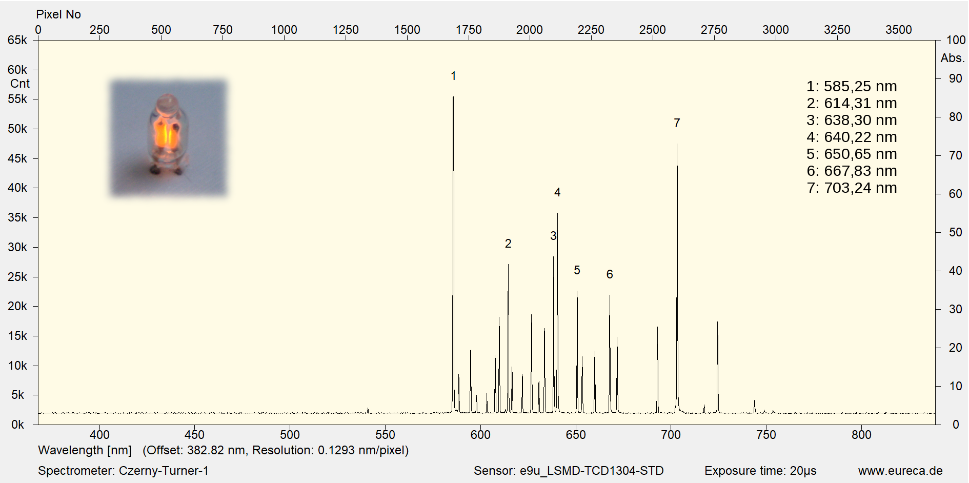
- Instead of using Excel/Matlab to calibrate the wavenumber scale in step 11, the SpectrumAnalyzer software has a convenient calibration function (which is also mentioned in the assembly Youtube video). The neon spectrum has a great reference image here: https://www.eureca.de/files/spektrum-gl ... ll-neu.png (the neon spectrum image in the instructions is unfortunately not displaying on the open-raman.org website). The key is that the huge leftmost peak should be at 585nm in the result, and the RMS output of the calibration should be around 0.001nm or so (from my experience so far).
- Enclosure:
- For laser safety reasons, I wanted to have the entire unit in a light-tight enclosure. With the liquid or solid cuvette installed, the overall dimensions needs to be around 400x180x180mm, if we want to comfortably reach the laser power switch and the alignment knobs. I ended up finding this one on Amazon that was basically a perfect fit: https://www.amazon.ca/dp/B0F4JY2RGF?ref=fed_asin_title
- I drilled out some holes for the TR75/M optical posts at the bottom of the enclosure, then mounted the entire spectrometer using those holes. The Ethernet and power cord exits through a single hole that is sealed with a generous amount of opaque tape.
- Other notes:
- Minor note: the light cover doesn't have its own STEP file, but you can easily extract this from the assembly's STEP file.
- The Youtube assembly video for the starter edition was super helpful! https://www.youtube.com/watch?v=47Uw0OJH3Aw I highly recommend watching this for anyone who has only seen the text instructions on the website, but you'll likely need both the text and the video to fully understand all the steps.
- You can likely find all of the bolts used much cheaper at the hardware store, rather than from Thorlabs, but be careful to get the same head style, or else the head may not fit correctly.
- IMG_6157.jpg (414.31 KiB) Viewed 250861 times
- IMG_6238.jpg (378.32 KiB) Viewed 250861 times
- IMG_6234.jpg (436.08 KiB) Viewed 250861 times
* Pre-built versions of SpectrumAnalyzer that work with the FLIR Blackfly S, and the modified source code.
* Modified STEP files based on the upgraded liquid cuvette design.
* More photos of the assembly process, including the LDM21 wiring that I struggled with a fair bit.
Many thanks to Luc for making this so accessible, even to home hobbyists that are new to optics!
